In August 1858, Queen Victoria sent the first transatlantic telegram to U.S. President James Buchanan.
The cable system had taken a total of four years to build, and used 7 copper wires, wrapped in a sheath of gutta percha, then covered with a tarred hemp wrap and then sheathed in an 18-strand wrap, each strand made of 7 iron wires. It weighed 550kg per km, with a total weight of over 1.3Mkg. This was so heavy that it took two vessels to undertake the cable lay, and meeting in middle of the Atlantic, splicing the two cables together, then setting out east and west respectively. The result could hardly be described as a high-speed system, even by the telegraphic standards of the day, as Queen Victoria’s 98-word message took a total of 16 hours of attempts and retries to send.
But poor signal reception was not the only problem with the cable. The copper conductor was powered with a massive high-voltage induction coil producing several thousand volts, so enough current would be available to drive the standard electromechanical printing telegraph station at the receiving end. This, coupled with the weight and cost saving measure of using thinner copper wires, were important reasons for the cable’s receptions problems, and for its subsequent demise. To compensate for the deteriorating quality of the signal, the cable company’s chief engineer, Wildman Whitehouse, responded by progressively increasing the voltage applied to the cable system. In a DC system increasing the voltage increases the current, which raises the temperature of the copper conductor and in this case caused failure in the insulation, which obviously exacerbated the deterioration of the signal to a catastrophic extent. After three weeks, and just some 732 messages, the cable failed completely.
The cable company’s inquiry into the failure found that Whitehouse was responsible for the cable’s failure and was dismissed. But the problems were not solely due to Whitehouse’s efforts in increasing the voltage, but in poor cable construction in the first place. Not only did they use a thin copper conductor, but in places the copper was off centre and could easily break through the insulation when the cable was laid. A test sample was compromised with a pinprick hole that “lit up like a lantern” when tested, and a large hole was burned in the insulation.
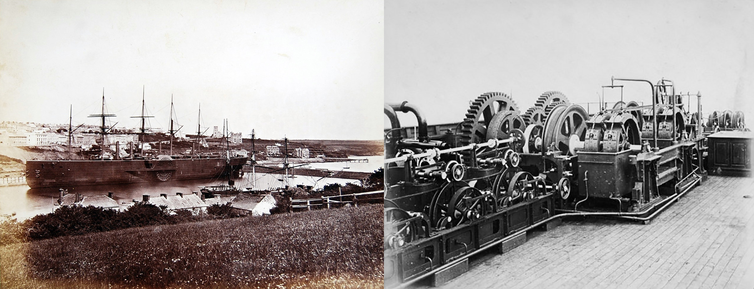
Figure 1 – Isambard Kingdom Brunel’s SS Great Eastern, the ship that laid the first lasting transatlantic cable in 1866
But this was not seen as a failure in the entire concept of trans-oceanic cables. It was an early proof that the concept was workable, but it needed a higher quality implementation. Perhaps more sensitive reception equipment, such as Thompson’s mirror galvanometer and siphon recorder. Perhaps thicker conductors, and larger cable lay ships to avoid at-sea splicing with its attendant cable handling issues. Similar to the railway boom some 10 years earlier, a flurry of companies formed to lay more undersea cables that very quickly wrapped the globe.
Throughout the 1860s and 1870s, British-funded cables expanded eastward, into the Mediterranean Sea and the Indian Ocean. An 1863 cable to Bombay (now Mumbai), India, provided a crucial link to Saudi Arabia. In 1870, Bombay was linked to London via submarine cable in a combined operation by four cable companies, at the behest of the British Government. In 1872, these four companies were combined to form the mammoth Eastern Telegraph Company, owned by John Pender. A spin-off from Eastern Telegraph Company was a second sister company, the Eastern Extension, China and Australasia Telegraph Company, commonly known simply as “the Extension”. In 1872, Australia was linked by cable to Bombay via Singapore and in 1876, the cable linked the British Empire from London to New Zealand.
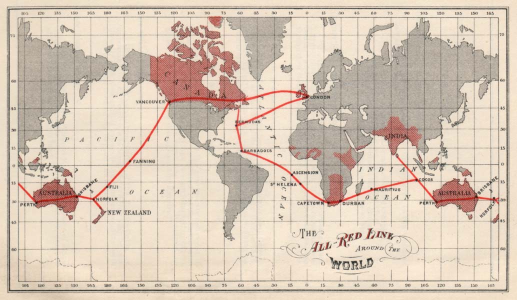
Figure 2 – Map of the All Red Line, c 1902
Immediately thereafter there were a number of pressures on this burgeoning new industry: make the cables more reliable, increase the reach of the cable system and reduce the cost of messages and at the same time increase the speed. We settled into a few decades of progressive refinement of the basic model, where improvements were incremental rather than meteoric. It was not until the early 20th century that message speeds on trans-Atlantic cables would exceed 120 words per minute.
In so many ways the commercial pressures for increased speed, reliability and reach have continued to drive the cable industry for the ensuring 150 years. The industry initially concentrated on metallic conductors for the signal, namely copper, matching the capabilities of the electric technology of the day. But metallic conductors have some severe limitations. There are noise components, frequency limitations, and current limitations. So, in the effort to increase the capacity of the cable system in response to the growing demands of telephony, we turned to fibre optic systems. The first transatlantic telephone cable to use optical fibre was TAT-8, which went into operation in 1988.
Fibre Optic Cables
There is a curious physical property of light that when it passes from one medium to another with a different index of refraction, some of the light will be reflected instead of being transmitted. When you look through a clear glass window you will see a faint reflection of yourself.
Depending on the angle of incidence of light meeting a refractive boundary, the proportion of reflected light can be varied. For low incidence light, the reflection rate can approach 100%, or total internal reflection.
References to the original work that describe this total internal reflection property of light appear to date back to the work of Theodoric of Freiberg in the early 1300’s, looking at the internal reflection of sunlight in a spherical raindrop. The behaviour of light was re-discovered by Johannes Kepler in 1611 and again by René Descartes in 1637 who described it as a law of refraction. Christiaan Huygens, in his 1690 Treatise on Light, examined the property of a threshold angle of incidence at which the incident ray cannot penetrate the other transparent substance. Although he didn’t provide a way to calculate this critical angle, he described examples of glass-to-air and water-to-air incidence. Isaac Newton with his 1704 corpuscular theory of light explained light propagation more simply, and it accounted for the ordinary laws of refraction and reflection, including total internal reflection on the hypothesis that the corpuscles of light were subject to a force acting perpendicular to the interface. William Wollaston in 1802 invented a refractometer to measure the so-called refractive powers of numerous materials. Pierre-Simon Laplace took up this work and proposed a single formula for the relative refractive index in terms of the minimum angle of incidence for total internal refraction. Augustin-Jean Fresnel came to the study of total internal reflection through his research on polarization. In 1816, Fresnel offered his first attempt at a wave-based theory of chromatic polarization. Fresnel’s theory treated the light as consisting of two perpendicularly polarized components. In 1817 he noticed that plane-polarized light seemed to be partly depolarized by total internal reflection, if initially polarized at an acute angle to the plane of incidence.
While the behaviour of total internal reflection had been useful in gaining a better understanding of the nature of light, it was still a solution in term of a practical problem. In 1842 a Swiss physicist, Jean-Daniel Colladon, demonstrated the use of a tube of water as a wave guide for light. This was also demonstrated some 17 years later by John Tyndall in 1859. The subsequent years saw these “light bending” experiments shift from columns of water to fine strands of glass (fibres).

Figure 3 – Daniel Colladon’s demonstration of total internal reflection of light in a water tube
It was not until 1930 when Heinrich Lamm invented the “medical endoscope” which was a bundle of fibres carrying light into the body, and fibre endoscopes became a common tool in the medical space. Some 30 years later, in 1965 we turned our attention to using guided light in the context of communications, when Manfred Borner of Telefunken in Germany patented the first fibre optic communication system. At much the same time STC’s Sir Charles Kao offered the perspective that if we could device of a combination of glass fibre and a light source that had a loss rate of less than 20db per km, then the result would be a communications system that could compete cost effectively with existing metallic conductor cable systems.
20db per kilometer?
Loss is measured in decibels, which is a logarithmic unit. A loss rate of 10db per kilometre is equivalent to a degradation in the signal of 90% (1 in 10) while a loss rate or 20db is a degradation of 99% (1 in 100).
At 20db/km a 10km fibre cable has a transmission rate of 1 in 1020. A 40km cable has a transmission rate of 1 in 1080. A photon may be small, but that’s still a lot of photons! By the time you try and push this 20db/km cable beyond 42km you need to inject more photons than exist in the visible universe to get even 1 photon out!
In Kao’s vision, he was probably thinking about very short cable runs indeed!
In 1970 a team at Corning made a fibre that had a loss rate of 17db/km with a light source of 630nm (this 3db gain is the same as halving the attenuation of a 20db/km system). This introduction of low loss fibre was a critical milestone in fibre optic cable development. In work on how to further reduce this loss rate, it was noted that longer wavelengths had lower rates. This led to work in the early 1970’s to increase the wavelength of the light source, using near infrared light. There were also experiments with changing the doping agent in the fibre from titanium oxide to germanium oxide. With these two changes, using a 850nm light source (instead of 630nm) and fibre cable with germanium oxide doping, the achievable fibre loss rate dropped to less than 5db/km, which is a truly awesome change in the loss profile! This 12db drop is a 16-fold improvement in the ‘transparency’ of the fibre. This result is close to the theoretical minimum attenuation at 850nm, and the effort then concentrated on using light sources with even longer wavelengths. By 1976 we had developed laser light sources that operated at 1200nm, which could drive fibre with an attention of less than 0.46db/km, and by the end of the 1970s they were using 1550nm lasers and achieving less than 0.2db/km.
Why is 1550nm important?
The fundamental loss limits for a silica-based glass fibre are Rayleigh scattering at short wavelengths and material absorption in the infrared part of the spectrum. A theoretical attenuation minimum for silica fibres can be predicted at a wavelength of 1550nm where the two curves cross (Figure 4). This has been one reason for laser sources and receivers that work in this portion of the spectrum.
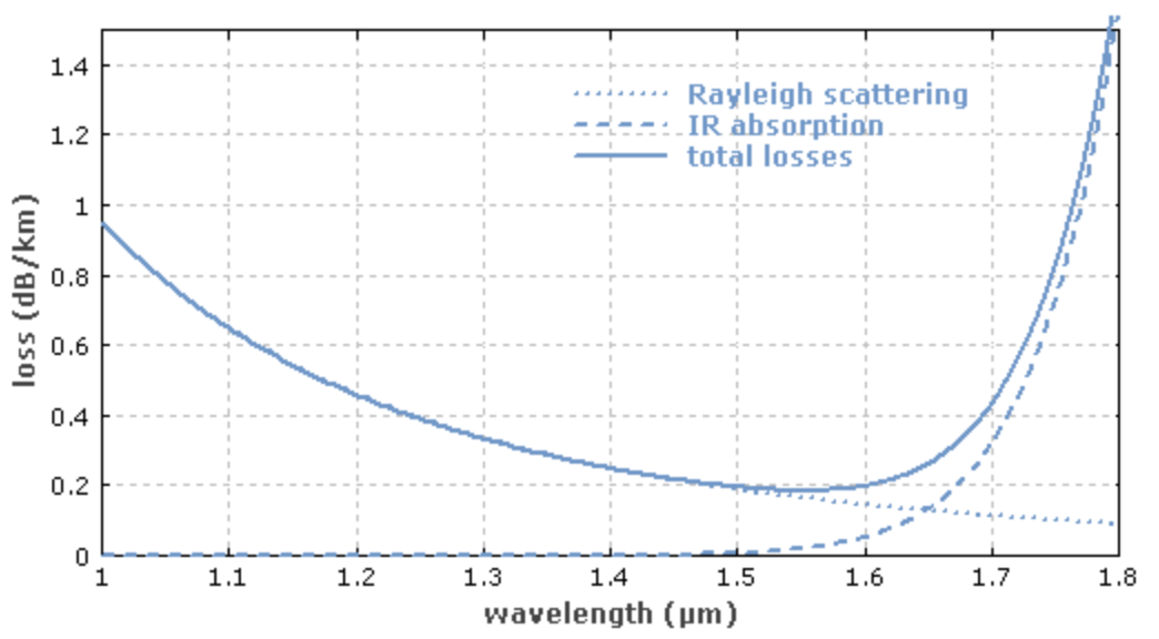
Figure 4 – Loss Profile for Silica Fibre
One area of refinement in recent work in germanium-doped silica-based fibre has been in reducing the water loss peak at 1383nm. Conventional single-mode fibres have very high loss rate at this wavelength because the fibre absorbs OH ions during manufacturing. This water loss point can continue to increase even after cable installation. The high attenuation makes transmission in this particular spectral region impractical for traditional single-mode fibres. There are two types of fibres that address this limitation: Low Water Peak (LWP) fibres, which lower the loss in the water peak band of the spectrum, and Zero Water Peak (ZWP) fibres, which eliminates the heightened loss at the water peak line.
Semi-Conductor Lasers
A parallel thread of development has taken place in the area of semi-conductor lasers.
This work can be traced back to a period of a renaissance in physics at the start of the twentieth century. In 1917 Albert Einstein described the concept of stimulated emission, where if you inject a photon of precisely the ‘right’ wavelength into a medium containing a collection of electrons which have previously been pushed into an excited state, they will be stimulated to decay back to their original stable state by emitting photons of the same wavelength of the trigger photon, and this stimulated emission will occur at the same time for all of these stimulated electrons. It took another twenty years for this theoretical conjecture to be confirmed in an experiment conducted by Rudolph Ladenburg in 1937.
In 1947 Willis Lamb demonstrated stimulated emission in hydrogen spectra in a gaseous medium. Alfred Kastler then proposed the idea of optical pumping where shining light of a certain wavelength will push the electrons in the medium into an excited state which can then be triggered to emit stimulated emissions in a simultaneous manner. In 1951 Joseph Weber proposed the MASER, or Microwave Amplifier for Stimulated Emission of Radiation, which operated at the wavelength of microwaves, with direct application for radar applications, subsequently developed in 1954 by Charles Townes (Figure 5).
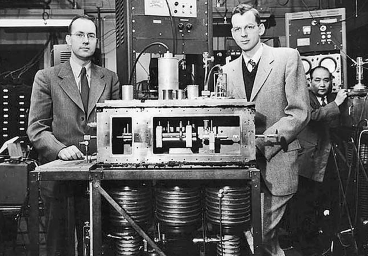
Figure 5 – Charles Townes (left) with the Maser he developed in 1954
In 1957 a group from Bell Labs theorised a MASER that operated at the frequencies of visible light, and they changed the name to Light Amplifier for Stimulated Emission of Radiation, or LASER, which was then demonstrated by Theodore Mainam in 1960 with a pulsed ruby laser. In this experiment the medium was a ruby crystal, and the stimulation was provided by a flashbulb. In 1962 Robert Hall proposed the use of semiconductor material as the gain medium and demonstrated the pulsed semiconductor laser.
The year 1970 brought all these ideas together into a practical device. It was a continuous operation device (rather than “pulsed”), that operated at room temperature (and not cooled by liquid nitrogen) and used a Gallium Arsenide semiconductor medium, demonstrated by Zhores Alferov, Izuo Hayashi and Morton Parish. These days the industry uses a number of alloys for semi-conductor fibre optic lasers, such as the InGaAsP semiconductor, which uses an alloy of gallium arsenide, gallium phosphide, and indium phosphide.
Further Refinements
The question was then how to make this approach scale to provide a high-capacity communications system. We had been through a similar path in telephony some decades earlier when trying to place multiple conversations on a single conductor. One approach was to multiplex the conversations and use a higher common base data rate and intertwine the signals from each conversation (time division multiplexing). Another approach is to use frequency division multiplexing and encode each conversation over a different base frequency. The same applies to fibre communications. The scaling options are to increase the data rate of the signal being encoded into light pulses, or to use a number of parallel data streams and encode them into carrier beams of different wavelengths, or even to use both approaches at the same time. Which approach is more cost effective at any time depends on the current state of lasers and fibres, and the current state of the encoding and decoding electronics (codecs) and digital signal processors (DSPs). More capable signal processors allow for denser encoding of signals into a wavelength, while more capable fibre allows for more wavelengths to be used simultaneously.
The period from 1975 to the 1990s saw a set of changes to lasers that allowed them to operate at longer wavelengths, with sufficient power to drive 10µm core fibre (single mode fibre, or SMF). These are single mode lasers with external modulators.
The next breakthrough occurred in 1986 where work in the UK by David Payne at Southampton University and the US by Emmanuel Desurvivre at Bell Labs both discovered the Erbium Doped Fibre Amplifier (EFDA). Long fibre runs require regular amplification (or repeaters). The optical repeater model used prior to EDFA was to pass the signal through a diffraction grating to separate out the component wavelengths, send each signal to an optical to digital signal processor to recover the original binary data, then pass this data to a laser modulator to convert the signal to an optical signal for the next fibre leg. Each wavelength required its own optical-electrical-optical amplifier. When a length of fibre is doped with erbium, and excited with its own pumped light, then incoming signals are amplified across the spectrum of wavelengths of the original signal. Rather than demuxing the composite signal into individual signals and amplifying them separately, an EDFA system can use a single piece of doped cable in a repeater to amplify the entire composite signal.
The implication of EDFA was that the amplification function was simplified, allowing high wavelength counts to be applied to a EDFA-based cable system without changing the repeaters.
Fibre Impairments
Modal dispersion is seen in multi-mode fibre. There are a number of paths through a large core fibre. Some paths use internal reflection off the edges of the core, while other paths are more direct without any internal reflection. The reflected paths are longer so a single square wave input pulse will be dispersed into a waveform that has a strong resemblance to a Gaussian distribution. Single mode fibre that uses a 8-9m core diameter does not have this form of signal impairment, because as long as the core diameter is sufficiently small, at no more than 10x the signal wavelength, the internal reflection paths are minimal compared to the path directly along the core.
Chromatic dispersion is due to the property that lower frequencies travel faster, and if a signal uses a broad spectrum of frequencies, then the signal will become dispersed on the transit through the fibre and the lower frequency component will arrive earlier than the higher frequency component. To reduce the level of signal degradation and increase the signal bandwidth G.655 fibre (the most common fibre used) was engineered to have zero chromatic dispersion at 1310nm as this was the most common laser source at the time. Signal dispersion can be compensated by placing dispersion compensating fibre lengths in every repeater, assuming that you wanted to compensate for chromatic dispersion (which in Dense Wave Division Multiplexing (DWDM) is not necessarily the case).
Polarisation mode dispersion. Silica fibre has small scale radial variations, which means that different polarisation components will propagate through the fibre at various speeds. This can be corrected by placing a Polarisation Mode Dispersion (PMD) compensator just in front of the receiver. This is performed after the wavelength splitting so one unit is required for every wavelength. This requirement of PMD compensation per wavelength was an inhibitory factor in the adoption of 40Gbps per wavelength in long cable systems in DWDM systems.
These three forms of optical impairments are shown in Figure 6.
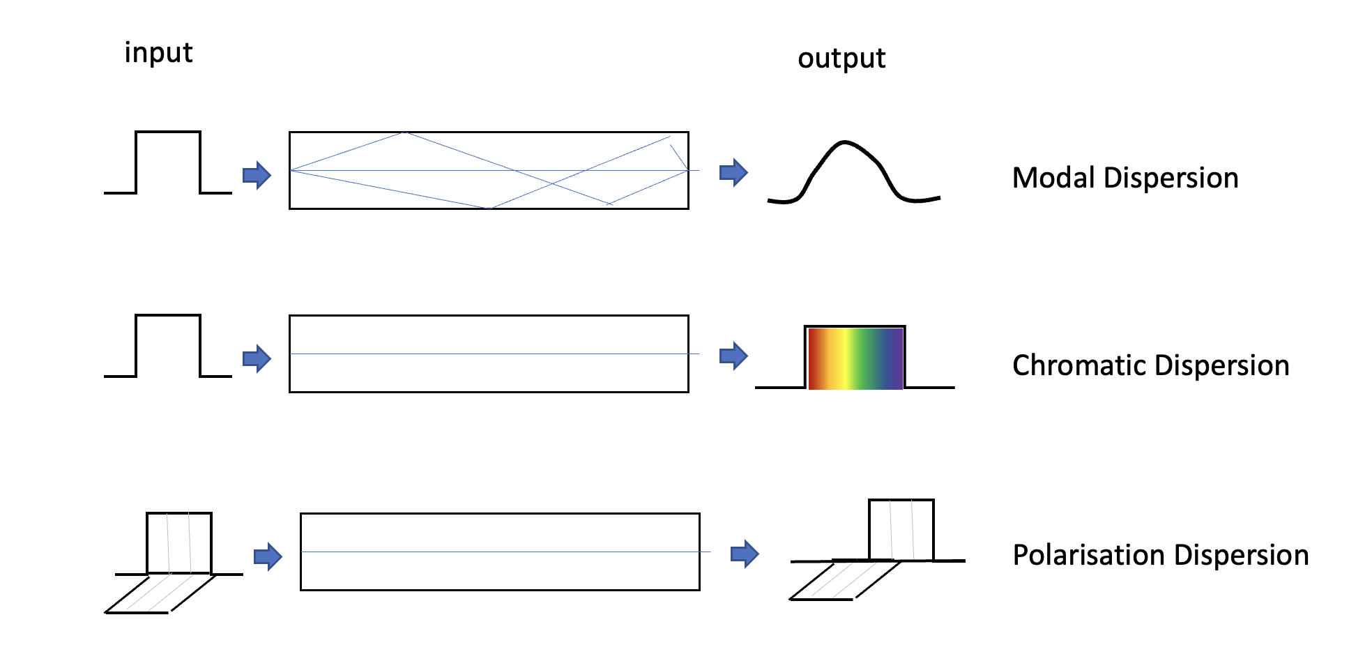
Figure 6 – Optical impairments
Non-linear effects. A linear effect is where the effect is proportional to power and distance, whereas non-linear effects are threshold based and only appear when a particular threshold is crossed. For linear effects a common response to compensate is to increase the input power, but for non-linear effects this will not necessarily provide compensation. This was first discovered in 1875 by Jon Kerr and was named the Kerr Effect. In a light pulse the leading part of the pulse changes in power very quickly and this rapid change causes a change in the refractive index of the medium if the optical power level is high enough. The result is that there is self-phase modulation where the pulse interferes with itself. In a Wave Division Multiplexed (WDM) system there is also cross-talk modulation, where the signals (pulses) in one wavelength interferes with the signals in other wavelengths, There is also four wave mixing where two wavelengths of sufficiently high power levels create two phantom side signals spaced equally apart, which will interfere with adjacent signals in a DWDM configuration.
The conventional approach to these non-linear effects was to limit the optical launch power (which limits the reach, or inter-amplifier distance in a cable run), and also to use cable with high levels of chromatic dispersion (so that the pulse energy is dispersed by chromatic dispersion effects) and to use a large effective core area in the fibre, both of which were properties of G.652 fibre.
In the search for longer reach and higher capacity of optical systems we have devised a new set of non-linear mitigations, which include Nyquist subcarriers, Soft Decision Forward Error Correcting codes. Super-Gaussian PCS and Non-linear compensation. All these techniques rely in improvements in the digital signal processing (DSP) in the transceivers.
In the 1980’s the G.652 fibre systems were suited to the 1310nm lasers that were used at the time. In the search for lower attenuation, we shifted to 1550nm lasers, which were placed at the minimum attenuation point for the media, but the large core area (80µm2) meant high chromatic dispersion which had to be compensated for with lengths of Dispersion Compensating Fibre (DCF), which effectively cancelled out the advantages of 1550nm lasers.
There was a brief time when we used G.653 DSF (dispersion shift compensating fibre), which used a narrower core to shift the zero chromatic dispersion point up to 1550nm. However, in the mid 1990’s we started to use DWDM systems, and here the aim was to have some chromatic dispersion to reduce the cross-talk factors in the fibre.
Today we tend to use G.655 Non Zero Dispersion Shift Fibre (NZDSF) that provides some level of chromatic dispersion at 1550 nm in order to reduce the cross-talk effects in DWDM systems centred around 1550nm, with a core area of 55µm2.
The next step was G.655 Large Effect Area Fibre (LEAF) with a larger core area of 72µm2. This is a variant of G.655 with a low band dispersion area, and a large effective area. This is a better configuration for single wavelength 10Gb transmission.
Coherent Technology
In 2010 coherent technology was introduced. This form of denser packing of the signal encoding into the signal through phase and amplitude modulation, borrowed from the earlier work in various forms of radio and voice digital models was now being applied to photons with the advent of more capable DSPs that exploited ever narrower ASIC track width and higher capabilities at constant power).
The first generation of all-optical systems used simple on/off keying (OOK) of the digital signal into light on the wire. This OOK signal encoding technique has been used for signal speeds of up to 10Gbps per lambda in a WDM system, achieved in 2000 in deployed systems, but cables with yet higher capacity per lambda are infeasible for long cable runs due to the combination of chromatic dispersion and polarisation mode dispersion.
At this point coherent radio frequency modulation techniques were introduced into the digital signal processors used for optical signals, combined with wave division multiplexing. This was enabled with the development of improved digital signal processing (DSP) techniques borrowed from the radio domain, where receiving equipment was able to detect rapid changes in the phase of in incoming carrier signal as well as changes in amplitude and polarization.
Using these DSPs it’s possible to modulate the signal in each lambda by performing phase modulation of the signal. Quadrature Phase Shift Keying (QPSK) defines four signal points, each separated at 90-degree phase shifts, allowing 2 bits to be encoded in a single symbol. A combination of 2-point polarisation mode encoding and QPSK allows for 3 bits per symbol. The practical outcome is that a C-band based 5Thz optical carriage system using QPSK and DWDM can be configured to carry a total capacity across all of its channels of some 25Tbps, assuming a reasonably good signal to noise ratio. The other beneficial outcome is that these extremely high speeds can be achieved with far more modest components. A 100G channel is constructed as 8 x 12.5G individual bearers.
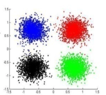
Figure 7 – Phase-Amplitude space mapping of QPSK keying
This encoding can be further augmented with amplitude modulation. Beyond QPSK there is 8QAM that adds another four points to the QPSK encoding, adding additional phase offers of 45 degrees and at half the amplitude. 8QAM permits a group coding of 3 bits per symbol but requires an improvement in the signal to noise ratio of 4db. 16QAM defines, as its name suggests 16 discrete points in the phase amplitude space which allows the encoding of 4 bits per symbol, at a cost of a further 3db in the minimum acceptable S/N ratio. The practical limit of increasing the number of encoding points in phase amplitude space is the signal to noise ratio of the cable, as the more complex the encoding the greater the demands placed on the digital signal processor.
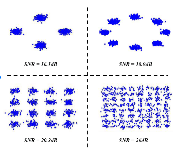
Figure 8 – Adaptive Modulation Constellations for QPSK, 8PSK, 16QAM AND 64QAM
There are two parts to this evolution. The first is increasing the base signal rate, or baud rate. The second is to increase the signal to noise ratio of the system, and the third is to increase the capability of the digital signal processor. Table 1 shows the result of successive refinements to coherent fibre systems since 2010.
| Year | Mode | Baud | Capacity/Lambda | Cable Capacity | DSP |
|---|---|---|---|---|---|
| 2010 | PM-QPSK | 32 GBd | 100G | 8T, C-Band | 40nm |
| 2015 | PM-16QAM | 32 GBd | 200G | 19.2T, Ext C | 28nm |
| 2017 | PM-32QAM | 56 GBd | 400G | 19.2T, Ext C | 28nm |
| 2019 | PM-64QAM | 68 GBd | 600G | 38T, Ext C | 16nm |
| 2020 | PS-PM-64QAM | 100 GBd | 800G | 42T, Ext C | 7nm |
| 2022 | PCS-144QAM | 190 GBd | 2.2T | 105T, Ext C | 5nm |
Table 1 – Coherent Fibre Evolution
Futures
We are by no means near the end to the path in the evolution of fibre optic cable systems, and ideas on how to improve the cost and performance still abound. Optical transmission capability has increased by a factor of around 100 every decade for the past three decades and while it would be foolhardy to predict that this pace of capability refinement will come to an abrupt halt, it also must be admitted that sustaining this growth will take a considerable degree of technological innovation in the coming years.
One observation is that the work so far has concentrated on getting the most we can out of a single fibre pair. The issue is that to achieve this we are running the system in a very inefficient power mode where a large proportion of the power gets converted to optical noise that we are then required to filter out. An alternative approach is to use a collection of cores within a multi-core fibre and drive each core at a far lower power level. System capacity and power efficiency can both be improved with such an approach.
The refinements of DSPs will continue, but we may see changes to the systems that inject the signal into the cable. In the same way that vectored DSL systems use pre-compensation of the injected signal in order to compensate for signal distortion in the copper loop, it may be possible to use pre-distortion in the laser drivers, or possibly even in the EDFA segments, in order to achieve even higher performance from these cable systems.
There is still much we can do in this space!